Lifestyle and Cleaning


Customized solutions developed and made in Europe
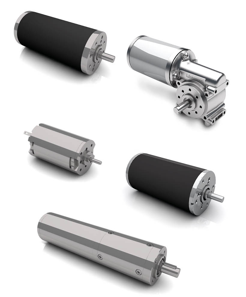
Powerful blowers in a compact package
Best-in-class energy efficiency system in line with the new Ecodesign Directive
Robust design and long service life
Long product availability

Better Together


  • Drive solutions from 1 to 5,000 W output power
  • Our smart drives in combination with a hub gearbox are perfectly suited as traction drives for autonomous, mobile cleaning machines
  • MAE's Thru-Flow and By-Pass blowers - as DC and AC versions, brushed and brushless, have been used for many years by renowned manufacturers
  • User-friendly - of course! Our products for household and cleaning appliances are compact and particularly quiet
Cleaning Machine
  • Cleaning Robots
    Fully autonomous cleaning robots with state-of-the-art drive technology are ideally built with batteries and charging ports. The combination of our traction drive and compact hub gearbox is particularly suitable for a small robotic cleaner design.
  • Scrubbers
    Classic walk-behind scrubbers or more comfortable ride-on scrubbers are suitable when large open areas need to be cleaned. Our blowers for the suction feature and efficient drives for the cleaning brushes ensure thorough but also gentle cleaning results.
  • Wet Vacuum Cleaners
    A wet vacuum cleaning can often aid in cleaning a particularly dirty soft surface such as a carpet or rug. Our blowers provide the necessary suction power and delivery perfect cleaning results..
  • Vacuum Cleaners
    Loud noise is both annoying and harmful for your health. For some years now, more and more emphasis has been placed on reducing noise pollution in both residential and commercial environments. Efficient and quiet blowers have proven themselves essential for this purpose in a wide variety of vacuum cleaner technologies.
  • Air Purifier
    The COVID-19 pandemic has made us more aware than ever before of the importance of clean air and how it relates to our health. In addition of production environments where air purifiers have been used for some time, these important tools are now increasingly being utilized in offices and public buildings. Reliable and especially quiet blowers ensure clean air without creating annoying and loud noises.
  • Kitchen Appliances
    Our motors are particularly useful in both modern large kitchen appliances as well as the catering industry because of their reliability and powerful performance in such a small package. You can find them in products such as mixers, blenders, food processors, coffee grinders, and much more.
October 15, 2025
AMETEK Magnetrol USA LLC Appoints TechStar LLC as Exclusive Channel Partner for Oklahoma
New Partnership Serving Oklahoma

AMETEK LMS has appointed a long-term channel partner, TechStar LLC, as its exclusive representative for the state of Oklahoma, expanding their coverage of our Magnetrol and Orion Instruments Product line.

Established in 2001, TechStar LLC is an industrial automation company that specializes in providing instrumentation and analytical devices. They position themselves as a Total Solutions Provider, offering complete solutions and turnkey offerings supported by subject matter experts for all process industries. Their services include 24/7 support, ongoing service and maintenance, and high-quality training options to enhance staff skills and operational efficiency. TechStar is dedicated to ensuring that their solutions run optimally and providing assistance throughout the implementation process.

Techstar_Oklahoma

TechStar has been a trusted channel partner of AMETEK LMS continuously providing commitment to quality and highest level of service to our shared customers as they grow their business with us in the US.

March 28, 2025
New Partnership Serving The U.S. Midwest Region

We are proud to announce that FCX Performance is now an authorized and exclusive representative for our Magnetrol® and Orion Instruments® branded solutions in the U.S. Midwest region. This partnership expands our presence across Illinois, Indiana, Iowa, Kentucky (Western Counties), Minnesota, Nebraska, North Dakota, South Dakota, and Wisconsin, ensuring greater accessibility to our innovative level and flow control solutions.


Blog Image FCX Partnership

With decades of experience and a strong reputation in process instrumentation, FCX Performance brings extensive industry expertise and a commitment to delivering exceptional service. Their local presence and technical knowledge make them the ideal partner to provide enhanced support, application expertise, and reliable product availability to our Midwest customers.

“We welcome FCX Performance to our growing network,” said Dennis Hungerman, DVP BU Manager at AMETEK® Level Measurement Solutions. “Their industry expertise and commitment to customer service align perfectly with our mission to provide innovative solutions and outstanding support.”

Customers in the Midwest can now benefit from faster response times, localized service, and expanded access to the full portfolio of Magnetrol and Orion Instruments-branded level and flow control solutions.

Please visit FCX Performance.com for all your AMETEK LMS (Magnetrol® and Orion Instruments® brands) needs in the Midwest.


We look forward to strengthening our service and support in the Midwest together with FCX Performance!


March 10, 2025
The New Old-Fashioned: Enhancing Traditional Level Measurement Techniques
For generations, the process industries have relied upon traditional level measurement techniques often stemming from mechanical principles. And why not? Entrusted, reliable, techniques that have been proven through decades of field use in the most demanding applications deserve user confidence. Traditional technologies include displacer level transmitters and sight glass level gauges, found throughout the energy sectors to this day with large installed bases. However, significant improvements have been made to innovate around these core principles to create something far more efficient for processes while decreasing total cost of ownership. Starting with buoyancy-based products,floats and displacers have long held their place in demanding applications including high pressures, temperatures and corrosive environments. Many tank farm and terminal operators employ displacer switches on storage tanks as fail-safes for hydrocarbon liquid and floating roof detection due to their versatility and durability in these applications earned through decades of service.  With a similar operating principle, displacer switches are transformed into continuous transmitters using torque tubes and LVDT-based technologies. These transmitters provide users continuous visibility into their desired level span most often through measuring an analog output (current / 4-20 mA) proportional to their 0-100% range. Torque tubes represent the majority of displacer transmitters found in the field. While the traditional torque tube uses a torsion bar that rotates relative to the weight of the displacer in liquid to correspond to a level change, a more seamless design was innovated using an LVDT and range spring combination. The latter design has an LVDT core that moves as the spring is unloaded, which occurs as liquid level covers the displacer.  This core movement induces voltages across the LVDT secondary windings located in the transmitter enclosure and these voltages are then converted to a level output measured through the 4-20 mA current loop. The technology can be top mounted directly into the vessel or installed into an external chamber mounted to the outside of the vessel. AMETEK LMS engineer installing a Magnetrol® branded Modulevel® displacer level transmitter. Compared to torque tubes, the LVDT / range spring technology has proven to be more resistant to vibration, providing a more stable output resulting in better linearity and repeatability. Other factors contributing to the success of LVDT / range spring displacer transmitters include the linear structure of the physical design as opposed to the rotational torque tube. This design contributes multiple benefits, including reduced long-term maintenance costs; a smaller installation footprint for facilities with confined spaces; and the ability for the transmitter to be removed without de-pressurizing the tank. The last factor, being able to perform maintenance or replacement of the transmitter without shutting down the process, results in increased uptime and plant profitability. The transmitter itself is an important element in the system, capable of advanced diagnostics while providing extreme ease-of-use through an intuitive user interface with quick-start menus to get processes up and running in a timely fashion. Make no mistake, these old displacers are “smart” transmitters built upon years of feedback and experience in the field. Another basic, yet important, traditional method for level measurement has been through visual indication of the liquid level. Providing visual indication becomes more complex in the process industries where extreme properties and corrosive environments come into play.  Nevertheless, visually inspecting the level is a technique that is still often used during walk-throughs, process start-ups, or to provide a degree of redundancy alongside other level instrumentation in applications such as storage tanks, separators and boilers. Whether it be petroleum refineries or power plants, sight glass gauges are the most prevalent method of visual indication. However, users familiar with sight glass gauges may encounter problems such as breakage, leaks, or bursting particularly at high pressures and temperatures.  In addition, the visibility of sight glasses can be poor and often affected by moisture and corrosion. Sight glass gauge vs an Orion Instruments® branded Atlas™ magnetic level indicator. An alternative technology used in place of sight glasses and now commonly specified in greenfield and brownfield projects is the magnetic level indicator (MLI) or magnetic level gauge. MLIs utilize a magnetized float inside of a chamber, which is isolated from a visual indicator and mounted to the outside of the process or storage vessel. The indicator has enclosed flags or a shuttle that are magnetically coupled to the magnets inside the float. The float follows the liquid level inside of the chamber, providing a clear representation of the liquid level as the indicator flags flip or the shuttle moves with the float. Boiler feedwater application upgraded from sight glass assemblies to Orion Instruments® branded Atlas™ magnetic level indicators. One of the biggest differentiators with MLIs from sight glasses is the isolation of the visual indicator from the chamber and therefore the application media, eliminating the ramifications of these fluids coming into direct contact with the indicator. The viewing window of the indicator is often produced using a polycarbonate, providing better shatter/impact resistance compared to glass as well as reduced UV sunlight exposure. There will be process temperature limitations when using polycarbonate, where glass is still required at extreme high temperatures. Other parts of the MLI can be provided in various plastic constructions for chemical compatibility purposes including the chambers and floats. When adding up these differences and evaluating typical repair costs of sight glass gauges, including the seals/gaskets, glass kits and labor for removal and replacement, it amounts to thousands of dollars in maintenance compared to MLIs. This does not include the negative impact to plant revenue and profitability due to process downtime during sight glass repair. An additional benefit of MLIs is the ease of implementing level transmitters or switches if an output proportional to the liquid level is required in addition to the visual indication. This can be beneficial as a measure of redundancy or if it is simply desirable to output the tank levels into a PLC or DCS. The most common level transmitters supplied through MLI designs are Guided Wave Radar (GWR) and Magnetostrictive. Both GWR and Magnetostrictive technologies can be deployed using a dual chamber design, having the advantage of isolating the level transmitter from the MLI if maintenance must be performed on the transmitter. Alternatively, single chamber designs are available allowing both visual indication and continuous level output. This can be accomplished by externally mounting a Magnetostrictive probe to the outside of an MLI chamber (utilizing the same float for measurement) or installing a GWR probe directly into the chamber. In the case of GWR, a probe is installed parallel to the MLI float and separated by a baffle plate inside the chamber. The use of GWR provides an additional degree of redundancy, as the GWR transmitter operates independently from the float (if the float gets stuck or damaged) and conversely there is no effect on the MLI if the level transmitter signal becomes lost. Alternatively, or in addition to level transmitters, level switches can either be clamped to the side of the MLI chamber (also operating off the float) or installed into the chamber using ultrasonic switches. Of course, switches provide an on/off detection for low and/or high levels as opposed to continuous level measurement from a transmitter.                   Magnetrol® branded Eclipse® 706 GWR transmitter installed next to an Orion Instruments® branded Atlas™ MLI with a Jupiter® JM4 magnetrostrictive level transmitter (midstream gas processing). The prevalence of these mechanical-based technologies still in use today prove not only their reliability at the outset, but their continued refinement through the years to keep them in a competitive position against many newer level instrumentation technologies. And based on the comfort and familiarity they provide users all over the world in some of the most demanding process industry applications, chances are they will continue to remain top-of-mind when specifying level instrumentation in the next generation of industrial facilities to come. 
February 24, 2025
Cut Monitor Technologies and Factors that Affect Their Performance
Measuring the percentage of water in oil (water cut) is required for both upstream and downstream oil production. Several technologies currently are used to measure water cut across a full range of applications. This article offers a basis of comparison, including advantages and disadvantages of each. Technologies Four basic on-line analytical instrument technologies are used to measure the percentage of water in oil: Capacitance, Microwave, Spectroscopy, and Density. All four rely on electrical and/or mechanical characteristics of the fluid. Because of the differences in each methodology, users should have at least a basic understanding of the strengths and weaknesses of each to select the right instrument for an application. Capacitance Capacitance technology has been used successfully to measure water cut for more than 40 years. Its success is due to the significant difference in dielectric constants between oil (k≈2.3) and water (k≈80). Figure 1 shows the sensing element, with diameter ‘a’, and the pipe wall, diameter ‘b’, that form the two plates of a cylindrical capacitor. Figure 1: Standard cylindrical capacitor The system’s electronics transmit a radio frequency voltage to the sensing element that measures changes in capacitance. As the amount of water in the flowing oil increases, the net dielectric of the fluid increases causing the capacitance to increase. The instrument’s onboard electronics then computes the relationship between capacitance change and water cut. Key advantages of capacitive instruments are a stable (and proven) measurement technology, simple design, insensitivity to water conductivity, and an ability to handle a majority of oil patch applications. In addition, capacitive instruments are typically among the lowest cost options relative to other measurement technologies. Disadvantages include difficulty in handling changing process factors and limitations in measurement range. Capacitive instruments are limited to water cut ranges that are below the inversion point of oil and water. As the fluid becomes water continuous, conductivity dramatically increases, creating an electrical short to ground. The short to ground drives the capacitance to infinity and obscures the dielectric information. This typically occurs at approximately 50% water cut in light oil and at 80% in heavy oil. Microwave This technology relies on the different electrical properties of the oil/water mixture to determine the water cut measurement. An oscillator transmits a microwave signal at a precise frequency via an insertion probe that travels through the fluid. As the percentage of water in oil rises, the microwave signal changes in amplitude and frequency. That change in signal is measured electronically, and the relationship between microwave signal change and water cut determined. Advancements in microwave technology have provided this methodology with several distinct advantages. Two of them are accuracy in the lower cut ranges and the capability to measure the full range of water cut (0-100%). Microwave-based systems also are more robust in handling process factors that can negatively affect other water cut measurement technologies. Disadvantages include its high initial cost relative to other technologies and sensitivity to salinity changes in the higher cut ranges. Spectroscopy The basic principle behind spectroscopic measurement of water cut is the response of an oil/water mixture to light. A spectroscopic device emits an infrared beam that ignores the water phase of the mixture. The sole reactant to the selected wavelength is the oil phase. Signal receptors on the device, shown in Figure 2, measure the absorption, reflection, and scatter of the infrared beam and makes a direct correlation to water cut. Figure 2: Signal receptors for spectroscopic water cut device Spectroscopy offers several advantages. First is its ability to measure across the full range of water cut. The percentage error actually decreases as the water cut increases. The technology’s accuracy at the high end of the cut ranges separates it from other competitive technologies. Another advantage is the technology is unaffected by changes in density, salinity or entrained gas. A major disadvantage is the lack the necessary accuracy at the lower cut ranges. That lack of accuracy limits the number of suitable applications. For example, it is not a good choice for Lease and Automatic Custody Transfer (L.A.C.T.) sites that have cut ranges of 0-3% water in oil per API Specification 11N. Users of infrared devices also must recognize that these instruments have a very defined sampling region. The sampling region emits an infrared beam that is reflected, absorbed, and scattered over a potentially small representative region of a very large sample and may or may not provide a true measurement of the entire process flow. Density Density measurement is the only methodology that uses a mechanical solution to measure water cut. Usually a coriolis flowmeter performs the measurement. Fluid enters flow tubes that are mechanically driven to vibrate at a certain frequency. Figure 3 provides a typical arrangement. As the fluid’s density changes, the frequency at which the tubes oscillate also changes. The water cut can be determined from those changes. Figure 3: Coriolis flowmeter Density measurement does provide the ability to measure the full range of measurement. The technology is cost effective and provides additional information (flow rate, temperature, and density) that can be used as input for process optimization. A drawback occurs when process variables start to change. Introduction of gas and salinity into the process immediately effects the water cut measurement and can significantly impact the accuracy of the device. It is typically confined to light oils due to the limited difference in density between water and heavy oil, and it encounters additional uncertainties when applied to water-flood enhanced oil recovery processes. Individual Product Capabilities If choosing the right technology weren’t difficult enough, it is useful to keep in mind additional instrument characteristics. Range of Accuracy: Some technologies are limited to certain cut ranges. Spectroscopy-based instruments are able to measure the whole range and increase in accuracy at the higher cut ranges. However, that technology is not useful for accurate, low-range cut measurement. On the other hand, capacitance devices offer excellent accuracy and repeatability at the low-cut ranges but are limited by the water/oil inversion point. Microwave measurements offer accuracy throughout the entire range, and their premium price reflects that capability. Communication Output: While all instruments provide the standard 4-20 mA output, some manufacturers have equipped their devices with additional capabilities. Utilizing digital protocols, embedded relays, multiple 4-20 mA signals and wireless communications are just some of the output options provided. Sensor Design: Various mounting options are available. Among the most common is the dual flanged spool piece. Figure 4 provides a typical arrangement. A different approach taken by some producers are threaded NPT and slipstream designs that permit a more customizable solution than a spool piece. Figure 4: Spool-piece cut monitor Maintenance also should be considered in choosing a sensor design. Users should ask if the probe is susceptible to paraffin buildup. How easy is the device to clean and/or replace? Does the sensing device measure a representative sample of the fluid? Are there any seals, coatings, or fittings that require regular replacement? How well the external electronics stand up to harsh ambient conditions? An insertion probe that can be installed directly in the process stream offers additional advantages when evaluating sensor designs. The insertion probe used by some capacitance devices allows the sensor to acquire samples over the entire length of the probe, providing a larger representative sample of the mixture and creating a capacitive-averaging effect that allows the electronics to calculate a more accurate measurement. Net Oil Calculation: Net oil calculations are gaining in popularity with the integration of computing devices, PLCs, flow meters, and water cut instrumentation. A packaged net oil calculation offers end users a dedicated system that eliminates the need for users to piece together individual components to compute net oil calculations. Start Up and Commissioning: Knowledge and experience are required during installation to get the best performance from a unit. With the increasing complexity of the technologies involved, the level of service and support an OEM provides is of great importance in choosing a device. Price: Price varies significantly from $7,000 to $60,000 and depends largely on the capabilities of a device. Such extras as digital communications and net oil calculations may add significantly to the base price of the unit. Conclusion To ensure the best performance and value from a cut monitor, users need to have comprehensive data on the process parameters and product characteristics that influence performance. Systems should be evaluated on the basis of accuracy, sensing range, process characteristics, mechanical configuration, maintenance requirements, and price prior to a purchase. Armed with right information on the advantages and disadvantages of each technology, users should be able to make the best decision to fit their needs. Learn more about Drexelbrook water cut monitors here or visit our Drexelbrook Learning Zone!