Mechanical flow switches
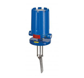
F10: Force of liquid or gas flow against a vertical flow vane mounted in a line causes the vane to pivot to a horizontal position, moving an attraction sleeve into the field of a switch magnet. This pulls the magnet toward the sleeve and actuates the switch.
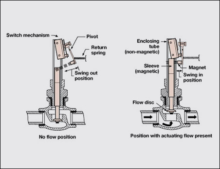
F50: The force of liquid flow through a valve body and against a flow disc causes it to lift out of the flow path. The attraction sleeve at the top of the disc assembly moves into the field of a switch magnet, attracting the magnet and actuating the switch.
F10: Vane actuated flow switch basic operating principle
Flow through the horizontal pipeline causes the pivoted mechanical flow switch vane assembly to swing in the direction of the flow, lifting an attraction sleeve to actuate the switch.
The O-ring sealed adjusting screw in the top of the enclosing tube compresses the range spring located above the attraction sleeve. Turning the adjusting screw clockwise increases the rate at which the flow switches actuate. Adjustments can be made while the flow switch is in service.
F50: Disc actuated flow switch basic operating principle
The rate of flow through the valve body raises or lowers the disc. This in turn raises or lowers the magnetic sleeve, within its sealed non-magnetic enclosing tube. On an increasing flow rate, the magnetic sleeve rises into the field of the permanent magnet, located outside the enclosing tube, actuating the attached switch mechanism. When the flow rate drops below the rate for which the flow disc is calibrated, a reversal of this action occurs.
Discover our mechanical flow switches


Do you want to learn more about our mechanical flow switches?
Contact your local AMETEK Level Measurement Solutions representative!
or contact us with any questions.
Find my local representativeRelated articles

AMETEK Magnetrol USA LLC Appoints TechStar LLC as Exclusive Channel Partner for Oklahoma

New Partnership Serving The U.S. Midwest Region

The New Old-Fashioned: Enhancing Traditional Level Measurement Techniques
