Electrostatic Hazards in Granular Bins
When assessing the safety of a storage tank, which contains an ignitable, insulating granular, or one that produces an ignitable dust or vapor, there are two sources of ignition to evaluate:
1. The energy available from equipment attached to the vessel, such as instruments, pumps, dust collectors, and actuators.
2. The energy developed by the process itself.
Item #1 is the area in which we have excelled for many years. Namely, producing an instrument that is incapable, even under failure conditions, of injecting unsafe levels of energy into the process. This is the area where we spend so much effort to satisfy the ATEX, FM, and CSA requirements. It is STILL the responsibility of the system designer to be sure that the correct instrument is selected for the specific hazards involved, and that it has the approvals his political environment requires.
Item #2 is STRICTLY the responsibility of the system designer, since the equipment manufacturers have no control, and generally no usable information, with which to evaluate whatever risks may exist. Regardless, it is desirable for instrument manufacturers, such as AMETEK Drexelbrook to aid their customers in achieving safe, as well as reliable, installations. The most common energy form developed by processes is electrostatic discharge (ESD), which can ignite certain dust or vapor clouds.
Since we have neither the technical competence nor the requisite information to evaluate this energy source, the best we can do is offer the applicable technical detail regarding our product, and indicate ways to avoid problems. THAT is the purpose of this message. We have been quite successful over the years in preventing the destruction of our electronic units by high levels of ESD. This usually involves the use of our “Heavy Duty Spark Protector”. Unfortunately, this device cannot prevent discharge from occurring; rather it expedites shunting of the electrostatic energy to ground.
The type of ESD problem, for which “capacitance probes” are unfairly singled out as a cause, is the “protruding ground”. This is strictly a geometry problem, and
can only be dealt with by the system designer. The problem includes any metallic element, which fails to provide a uniform vertical ground, from a location close to the tank bottom. Examples of the uniform vertical ground would be tank walls, stilling or gaging wells, vertical baffles, and continuous probes. A most egregious example of the “protruding ground” problem would be a tuning fork, rotobindicator, thermowell, or capacitance probe, mounted vertically downward, in the center of a plastic pellet silo.
The plastic is a great insulator; so blowing it into the silo will produce significant static charge. Even though (as is often the case) no amount of static discharge may contain enough energy to ignite the pellets, there is the possibility that dust, generated by transport, may be ignited at a considerably lower energy level. As the level approaches the high level instrument, the charged pellets will be able to arc to the “grounded” metal. This spark can be sufficiently long, to ignite the dust/air mixture. Even with dusts that won’t ignite, an additional hazard could be flammable vapor (hexane for example) carried over from a previous processing operation. Specific process materials to examine include: plastic powders and pellets, waxes, VERY dry food items, explosives, and dry nitrate fertilizers.
It is important to note, that although our probes would be incapable of measurement if shorted to ground, they LOOK like ground to Static Charge. If you check the probe-to-ground resistance of our instruments with an ohmmeter, you will find less than 200 ohms. This is because of the protection diodes in all our designs, which are essentially open circuits at the low voltage levels where the instruments operate. Since the first rule for dealing with static is to “bond everything to ground”, It is important to understand that both our center rod and Coteshield ARE grounded, as long as the mounting is not insulated from the tank, or the electronics disconnected. Where static charge is concerned, a 1 megohm path to ground is generally recognized as sufficient to nullify it!
There are ways to avoid the protruding ground geometry. The most obvious one is to use a continuous measurement, so that the probe represents a uniform vertical ground to the process.
Real life often dictates that high level switches MUST be used. The use of our flush probes (700-0207- family) makes the sensor part of the wall, and satisfies the uniform vertical ground condition. It also precludes problems with mechanical loading, at the cost of higher instrument price and more involved installation.
Insertion probes can be used, if mounted within 3 inches of the tank wall, a vertical baffle, cable, or pipe. The presence of these uniform vertical ground objects reduces the charge voltage in the area, sufficiently to prevent an arc from occurring. A probe of ANY length mounted upwardly, from the bottom of the bin, is also incapable of being a “spark promoter”.
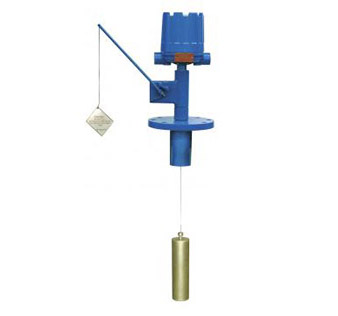
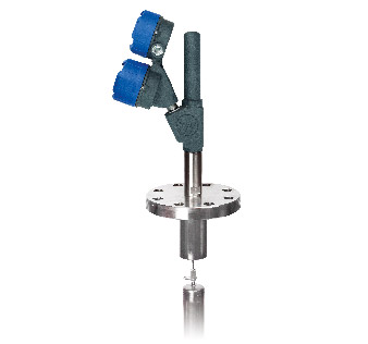
It may come as a shock to some who have been using paddle wheels, tuning forks, and servo plumb-bobs for years, to learn that these items are “spark promoters”. By planning for the static discharge that a particular process will produce, the correct instrument can be selected and political, as well as safety problems avoided.
Related products
Other applications
Do you want personal advice for your specific control process?
Contact your local AMETEK Level Measurement Solutions representative!
Find my local representative